
ArduOne, the 8051 development board

Board description
ArduOne is an 8051 based development board equipped with a P89C51RD2HBA from NXP, formerly Philips. This microcontroller compared to the basic version has a total internal RAM memory of 1Kbyte and an additional internal counter capable of generating up to 5 PWM signals on as many output pins. The internal code flash memory is 64Kbyte wide and the device can be easily programmed through the serial port properly connected to a PC. The serial port serves both for programming and as a serial input/output port for the loaded program. All the input/output pins of the 4 ports (P0 .. P3) are directly connected to the side connectors of the board, while a 4-pin microswitch is used to set the microcontroller in programming mode or in execution mode. Arduone is programmable both in mnemonic assembly language, and using higher level languages. There are various compilers for different languages for ArduOne(and in general for the 8051 family of microprocessors). Among the most interesting that can be found on the internet there are; BASIC www.bipom.com/bascom51_down.php, Pascal turbo51.com or even Cobol www.keil.com/cobolad.pdf or PL / M www.bitsavers.org/pdf/intel/ISIS_II/121966-003_PLM-51_Users_Guide_Jan84.pdf There are also development environments available to program in C that also integrate a simulator to test the program before sending it to the microcontroller, also available on the net. In this website, however, we will only deal with programs written in C and in particular are going to use the free SDCC (Small Device C Compiler) compiler available and freely downloadable from sdcc.sourceforge.net. For a deeper understanding of the C language, a book is available in PDF format at the following link HERE, while for the C language implementation in SDCC a user guide is also available in the same SDCC page. I recomend you to read it to get the best from the sdcc compiler. As editor we are going to use TextPad, a relatively cheap editor that let you write in other programming languanges as well, and can embed, compilation and execution commands (SDCC for ArduOne excluded of course). For debugging there is also a simulator in the SDCC package named uCSim but I never tried it myself. I find much more convenient to directly activate the ArduOne serial port and use it for debugging, by sending or receiving from/to the terminal, messages in some breakpoint-like positions in the code. In this way, serial port becomes a kind of run time environment.
As you might see from the picture beside (trust me if you can't), ArduOne has a 11.0592 MHz Crystal clock. We this "strange" frequency because with that value the common baud rate frequencies are easily generated by the internal 8 bit counter. Any other crystal frequency can be used instead of that, providing that you change the counter settings to obtain usable baud rate. A good choice is 12MHz. With this frequency each instruction cycle by default is exactly 0.5 uS wide. When using machine code a precise time lapse can be calculated as multiple of this base being each machine instruction a multiple of this time period long. Depending on the internal settings, maximum crystal frequency can go up to 20MHz at 6 clock cycle/instruction or up to 33 MHz when the device is set to work with 12 cycles/instuction. Using the device default settings, using a 20MHz clock is like using 40MHz clock on a standard 8051 device.
Ports P1 and P3 have (see labels beside the left connector) alternative functions. For instance, P1 can be used as a whole 8 bit port or P1_0/T2 as external pulse source for the 16 bit counter 2, P1_1/T2EX can be used to control counter 2 or as additional interrupt signal source, P1_2/ECI can be used as external clock input for the 5 PWM signals and finally P1_3/PWM0 to P1_7/PWM4 can be used as 5 PWM source signals to control 5 analog loads as motors, lamps or any other power loads. P3 as well can be used as whole 8 bit port or interrupt source pins (P3_2/INT0 P3_3/INT1), input source for the two standard counters T0 and T1 (P3_4/T0 P3_5/T1). P3_0/TxD and P3_1/RxD are the pins used by the MAX232 level converter to communicate with the PC. By extracting the MAX232 from it's socket you can use these pins to connect directly your PC wirelessly using bluetooth both for programmin and as serial port, once connected a simple bluetooth interface to the board.
P0 and P2 are two additional 8 bit ports, their alternative function is to be used as interface for an optional external RAM up to 64Kbite wide. Since ArduOne does not use the control pin needed for this function (ALE (PSEN for ROM)) we will use these two ports as additional 8 bit ports. These two ports can be used directly as input port but if used as output ports a pull up resistor must be connected to each port pin.
How to use ArduOne
Since this board is called ArduOne, i.e. something supposed to be better then Arduino, we are not going to start with the classic blinking LED as Arduino users might expect. We go directly with the steps followed when learning a new programming language, namely write the first "Hallo world" program. If you buy ArduOne from this site or from Ebay you'll find exactly this same procedure described here below, on a small note inside the Arduino cardboard box. In the same box you'll find a USB power connector to use the USB port of any PC to feed the board with the 5V needed. Since USB connector is quite standard you can use any other USB power source like; mobile phone battery, small pack solar power devices with USB output and any other USB power source. There is no voltage regulator on board, thus no energy waste using any standard 5V power source. By using the the cable no wrong voltage or polarity swap mistake are possible.
So, to get your board up un running you have to follow the steps below:
- Download and install SDCC from sdcc.sourceforge.net and make sure you can issue the command sdcc from any directory by adding to path variable the path: C:/programs/SDCC/bin so that you can reach it from any directory.
- Download and install TextPad from www.textpad.com/ and add to the run command from Tools the following parameters: Commad:sdcc Parameters:$File Initial Folder:$FileDir in this way you can compile the file within the editor by hitting run
- Download and install FlashMagic www.flashmagictool.com// and play with it to get connected with ArduOne using a serial cable. You can use an USB to serial adapter cable.
Here is a table with all the common interfaces you can build with ArduOne:
| Project name | SDCC C File | Schematic | Description | Datasheet of peripherals | Photo and/or video |
|---|---|---|---|---|---|
| Hallo world | halloworld.c | Connect ArduOne to serial port | EN, DE, ES, RU, FR, ITA. | MAX232 , P89C51RD2 | None |
| Stepping motor | stepping.c | stepping.sch | Stepping motor | ULN2803APG , M42SP-5 | Video |
| Encoder | encoder.c | Move the mouse here | Encoder | EM14A0D | Photo |
| Potentiometer | potentiometer.c | potentiometer.sch | Potentiometer | 3540 | Photo |
| Siemens DLR1414 | DLR1414.c | Coming soon | Coming soon | DLR1414 | Coming soon |
| Morse encoding | morse.c | Coming soon | Coming soon | ABI-009-RC | Video |
| 7 segments LCD | lcdsimple.c | Coming soon | Simple LCD driver | LCD-S101D22TR | Video , Photo |
| I2C Memory | I2Cmem.c | I2Cmem.sch | I2C Memory | AT2402 | Photo |
| SPI Memory | Menu_93C46A.c | 93C46A_schematic.sch | SPI 93C46A | 93C46A | Photo |
| One wire | Coming soon | Coming soon | Coming soon | Coming soon | Coming soon |
| 8 Digits 7 seg. Display | 7SegDispWord.c | Coming soon | Coming soon | MAX7219 | Video |
| 32X8 LED dot matrix | MatrixDisplay_8X32.c | Coming soon | Coming soon | MAX7219-4-In-1 | Video |
| ADC0808 | ADC0808.c | ADC0808.sch | 8 ch. 8 bit adc conv. | adc0808-n.sch | Photo1, Photo2 |
| Colors | colors.c | Not needed | Terminal's color setting | Not needed | Photo1 |
| Delay | delay.c | Not needed | Simple delay function | Not needed | Photo1 |
| Roman | roman.c | See #define lines | Ancient's roman counter | 4X20 LCD | Video1 |
| SN76489 | SN76489.c | SN76489.sch | Using 3 tones of the Texas instrument SN76489 to play music. Noise generator has not been used in this code. | SN76489 , The_SN76489_Sound_Chip | Video1 |
| Queue | Queue.c | Not needed | A Queue data structure implemented using a circular array. Size is 128 but can be bigger using int instead of char. | Not needed | Not needed |
| shiftOut() | ArduOneSide.c | Schematic in Murano | Sending data to Murano using a shift operation and a shift register (schematic entry) on the Murano side. | Not needed | Video1 |
| Interfacing an old telephone dialing disk | Software | Connections | Using an interrupt service routine to count the number of pulses coming from a rotary telephone disk. | Not needed | Video1 |
| DCF77 Date and time radio receiver | Software | Connect receiver output to P0_0 of ArduOne | Receiving time and date data from the DCF77 receiver in Frankfurt. | Data distribution. | Video1, Photo1, Photo2 |
| Two way PS2 keyboard communication | Software | Connect clock to P1_0 and data to P1_1, use two 2K2 pull up resistors. | Receiving and sending data from and to a ps2 keyboard. The specific software runs a binary counter on keboard's LEDs to show both functions use but send data has a meaning if you want to change the keyboard's behavior. Avoid key release data sending for instance, or change the repetition time. Remember, when you send a command you should read and expect an 0xFA from the keyboard as acknowledge signal. Last tip | Document 1 | Video1, Video2 Photo1 |
| PS2 mouse interface | Software | Connect clock to P1_0 and data to P1_1, use two 2K2 pull up resistors. | Mouse works using the same protocol ps/2 of the keyboard but it expect some initializations before sending some data. Remember, when you send a command you should read and expect an 0xFA almost always from the mouse as acknowledge signal. | Document 1 | Photo1 |
| clock | Software | No need. | Clock using the board crystal as reference, see the top comments in the program for details. Using PuTTY you can use form feed "\f" in the printf parameters to keep the numbers steady in the upper left corner of the terminal's screen. | No need. | Photo1 |
| RTTY Decoder | Decoder, Transmitter | Demodulator | RTTY signal decoder using two monostable multivibrators as demodulator and a software to decode the signal. There is also a Transmitter software to simulate the output of the demodulated signal from the receiver. This last program could be also used as a real transmitter or to bild a beacon transmitter adding some hardware. | Documentation | Video1, Video2 |
| Dual channel DAC | Triangle Generator | DAC schematic | Dual channel DAC with an additional Z axix control to switch on and off the oscilloscope beam in case somebody want to draw figures on the oscilloscope. The DAC are used in a different way then the one described in the datasheet but using the resistor ladder as it should be usually used in any electronic course book. The clever guy that suggested this modification describes how he came to this conclusion in this web page: Daniel Tufvesson | AD7524 | Video1, Photo1 Photo2 |
| 128X64 LCD Graphic display | BMP viewer | Connections | Driving a 128X64 pixels monocromatic LCD display. the software is just an interface to the data stream from the array with this organization. There are two stages, one from 0 to 200 for the upper screen and another from 200 to 400 (all hex, so it's 1Kb all toghether) because to move in the lower screen from left to right you have to exceed in X direction. This is the trick. 0 to F in X moves within the upper screen, while 0x10 to 1F moves x in the lower screen. y is always a span from 0 to 0x1F. it doesn't go from 0 to 64 as you might think. It's really a messy display. If you want to display your own picture on the scree I found an interesting converter online. You can select edge level and dimension, in this particular case they must be set to 128 X 64 Image to BMP online converter | QC12864B(ST7920) | MarilynMonroe, TheAuthor, Connections |
| Serial super speed | 115200 baud rate | No need | Setting the serail port baud rate at 115200 by setting SMOD to 1 (double baud rate), and TH1 to FF (baud rate setting). This speed can be reached with a crystal of 11.0592 MHz only using a 6 clock speed device as in the case of ArduOne. | No need | No one |
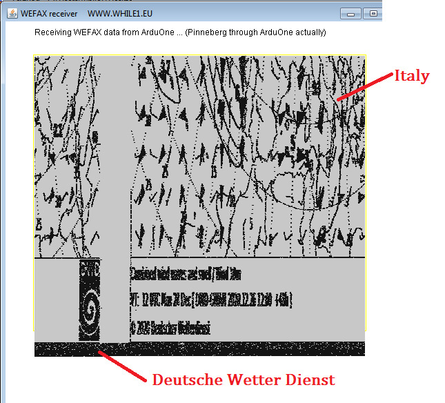
| WEFAX interface | SSTV_SimulatorHIRES.c, SchermoIntHRES.java | Same as the RTTY one | Receiving WEFAX images (isobaric maps) using ArduOne. Arduone sends a set of 480 samples for each line in half second. The samples are sent to a PC, using the serial port at a speed of 57600 baud. In the PC side collects the data and draws the image on the screen using a Java program. | sstv-handbook | Foto, Video, |
| PWM setting | pwm.c | Not needed | This is an example of how to use the 5 PWM channels of ArduOne. Notice that the body of the program is empty (while(1);) because the PWM generation, as for the other 3 counters, is an independent process. In this case the frequency is set at around 1.8MHz, that is 1/6 of the crystal frequency, producing a PWM frequency (1.8/256) of around 7.22KHz. To set other frequencies the output of counter T0 can be set as frequency generator or the signal can be read from an external pin using an external oscillator. The main program can modify any time the pwm percentace of any channel by simply writing in its register. The oscilloscope shows the channel 0 at 5% and channel 4 at 95%. | See the P89C51RD2HBA datasheet | pwm.jpg |
| Fluorescent display | io.c | Connections | How to define "int putchar(int)" function of SDCC <stdio.h> to use a FLIP fluorescent display as standard output with vertical scroll. | fluorescent | Video |
| I2C Scanner | I2C Scanner.c | Connect SDA to P1_0 and SDC to P1_1 | This program scans all the possible addresses of an I2C BUS, and returns the address of the ones that send an ACK (Acknowledge) signal. | I2C protocol, I2C Devices LINK | Photo1, Photo2 |
| Oscilloscope BMP viewer | bmp_viewer.c | DAC schematic | This hardware and software shows on the screen of an oscilloscope a black/white 128x64 BMP image. The two DACs make an interlaced scan of the image showing alternative the odd and even lines. This technique is used to reduce the flickering | -- | Photo1, Photo2, Video1 |
| AD5311 I2C interface | I2C_siemens_photomultiplier.c | -- | Controlling the 11 bit I2C DAC of a Siemen�s photomultiplier preamplifier. I can not publish the schematic of the preamplifier for obvious reasons, but the connections are strightforward. You just need to find the connections of the tiny DAC showed in Photo03. The software increases the only most significant 3 bits of the whole 0 to 3FF dynamic. This is done to show a stable picture on the oscilloscope. The AD5311 is used in this case to set the gain of a Siemen�s photomultiplier. | AD5211.pdf | Photo1, Photo2, Photo3 |
| Calculator with roman numerals | RomerRecnner3.c | -- | The official calcvlator of the roman empire is now ready. I had some problems with the fluorescent display but now it works. The numbers are directly converted in hexadecimal (because decimal sucks, do you agree? ). In the video I type my year of birth and my age. The numbers equal or less then zero are printed as "Nulla" or "Negativus" | See fluorescent display in this page | Photo1, Photo2, Video |
| MCP3001 SPI 11 bit ADC interface | MCP3001.c | See #define list in sw | Quick test of a 10 bit SPI ADC MCP3001 using #ArduOne . Vref is connected to +5V and in- to GND. This ADC will be used in a new handheld testing device. | MCP3001 datasheet | Photo1, Photo2 |
| Pluggable DAC module | dac_program.c | dac_schematic | Testing the easily pluggable new DAC minimodule for #ArduOne, #Murano, #Burano or any other digital device with an 8 bit parallel output, in this example a sine wave at 555Hz si produced using a LUT. The schematic doesn�t follow the recomandations explained in the datasheet, but it�s made in an easier way | TLC7524 datasheet | Photo1, Photo2, Photo3, Photo4 |
| Pluggable DAC module, other two functions. | cissoide.c, sinc.c, | The same of the DAC post above | These two program use the same pluggable DAC of the previous post, to show other two functions in the oscilloscope, a so called "Cissoide", namely a exp(-x)cos(x) function and a sinx(x), namely a sin(x)/x function. There is also a link to the two LibreOffice files used to produce the two look up tables. To transform a column from a .ods file into a row, I used Textpad in hexadecimal, replacing all the "NewLine" characters with commas ",". | cissoideValues_0+4pi.ods, sincValues-4pi+4pi.ods | Cissoide, Sinc |
| Uniform to normal random variable transformation. | gauss.c, | The same of the DAC post above | How to transform the uniform random variable produced by rand()
of SDCC into a normal (gaussian) random variable. To use rand()
you need to add |
no one | Video |
| Cavalieri-Simpson method for integrals calculation. | integer.c, floatRamo.c, | No one, just software | Calculating an integral using the Cavalieri-Simpson method. I believe the trapeze method is faster but you could try to use it if you know that the function to integrate is a polynomial of degree 2 or higher | Why Cavalieri? Explained here. | see SDCC C file |
| 40 mt. band beacon | beacon40.c | beacon40.sch | A 40 mt. radio amateur band beacon with 3 power level using a single TTL IC. The board is directly pluggable on an ArduOne, but any other microcontroller can be used. Warning! The parallel 220pF470pF must be replaced with a single 260pF and the coil should be a 1.85uH | What is a radio ham beacon? | Photo1, Photo2 Spectrum01, Spectrum02 |
| Writing an SDCC library | max7219a.c, max7219a.h, Tester.c | - | Description Sequence of commands to use in the consolle. | - | Photo1, Photo2 |
| 40 mt. band beacon, AM modulation | A2A.c, A2AF.c | beacon40.sch | Two examples of AM modulated signal using the same hardware of the CW 40 mt. band Beacon presented before. The moduklating signal is a 3 level sine wave that is actually a 3 level square wave but the result is good, especially if the bandwith of the receiver is narrow. Carrier is always present in this case, and the modulation percentage is 75% | What is AM modulation? | A2A, A2AF |
Working libraries
These libraries section let you use the functions developed for various interfaces connected to ArduOne. The idea is to avoid rewriting the same parts of code on each application. You can find the description of each function of the library in the header file, namely, the one with .h extension. The library file instead is the one you have to add during the compilation. So for instance the process to use the serial library will be:
- Copy serial.rel and serial.lst in the same directory of the main file.
- Compile the file containing the main function using the serial library like this: sdcc serialUser.c serial.rel
- Put the serial.h file in the same directory of the file containing the main function.
- Add directive #include "serial.h" (and #include <stdio.h> if you want to use printf with the serial port).
- Run the program. :-)
| Library | Reason | Header .h file | Library .rel and .lst files | Library use example | Comments |
|---|---|---|---|---|---|
| Serial port | Serial port functions | serial.h | serial.rel , serial.lst | serialUser.c | Defines functions void initSio() to initialize serial port, int getchar() to get a character and void putchar(int) to send a character to send a character. |
| MAX7219 | MAX7219 functions | max7219.h | max7219.rel , max7219.lst | max7219User.c | Defines functions void initMax7219() to initialize the display, void putchar(int) to allow the use of the function printf() of <stdio.h>, with all its formatting features and void setBrightnessMax7219(uChar) to set the display's brightness (0 to 15). | The complete functions list can be found in the max7219.h file.
| lcd | lcd functions | lcd.h | lcd.rel , lcd.lst | lcdUser.c | Defines functions void lcdInit() to initialize the lcd, lcdSetCursor20X4(x,y) to set the position of the cursor on the display void lcdPrint(char*) to print a string on the display lcdBarGraphInit() and lcdShowBarGraphValue(char) to initialize and show an orizontal bar graph on the LCD. This is a video to show you what I mean as lcd Bar graph BAR GRAPH. The complete functions list can be found in lcd.h file. |